![[Home]](/images/iso2mesh_2015_banner.png)
Example Scripts for Using iso2mesh
- 1. Demonstration for surf2mesh
- 2. Demonstration 1 for vol2mesh
- 3. Demonstration 2 for vol2mesh
- 4. Demonstration 3 for vol2mesh
1. Demonstration for surf2mesh
The sample script "demo_surf2mesh_ex1.m" is to demonstrate how to use surf2mesh for meshing a simple open-ended surface. The surface is saved in "surfmesh_demo.mat". Loading this mat file, you will find two variables, f, and v, they record a tube surface mesh. One can view this surface bytrisurf(f,v(:,1),v(:,2),v(:,3)); axis equal;
| The surface looks like |  |
then, we call surf2mesh to produce volumetric mesh from this surface. This includes 3 sub steps
- in the first step, the fine surface, f and v, are re-sampled to only keep 10% of the original elements
- because the surface has openings, in the second step, iso2mesh added a cubic frame outside the tube, and punch openings on the bounding box and merge with the tube surface to create a closed surface
- in the third step, a volumetric mesh is generated within the enclosed volume bounded by the bounding box and the tube.
| After step 1, the surface mesh look like | |
| After step 2, the surface mesh look like | |
| After step 3, the volume mesh look like |
I want to mention that at this point, iso2mesh can only mesh surfaces with their edges (borders of the open regions) strictly located within a bounding box surface. It can even handle the complex cases where a opening edge contour located on multiple sides of the bounding box.
2. Demonstration 1 for vol2mesh
The first vol2mesh demonstration is to create an FEM mesh from a CT scan of a rat-head. In this example, the volumetric data is a thresholded CT image of a rat. In a vol2mesh session, we first wrap the volume with a layer of zeros, in order to make the non-zero region close. Then we extract the boundary of the non-zero regions by calling matlab's isosurface(). The created isosurface, in the resolution of voxel sizes, will be resampled to specified mesh density. Before and after the simplification, we perform a mesh validation and repair process to avoid the appearance of "non-manifold" nodes. Once the surface mesh is completed, we produce volumetric mesh within the region bounded by the resampled surface mesh.
| The voxelated mouse head binary image looks like |  |
| The resampled mouse surface mesh is shown below |  |
| The cross-section of the 3D volumetric mesh looks like |  |
3. Demonstration 2 for vol2mesh
In this example, we try to make a little bit fun using iso2mesh while showing off the extreme flexibility and simplicity of making a complex mesh using this toolbox. We will make a mesh on a slab-shaped object with "ISO2Mesh" etched on one of the surface, just like the header image of this document showing.To make this "object", we first create a black-white image, "iso2mesh_bar.tif", with an image editor. This image is then read as a 2D array into matlab, we then invert the 0-1 values, and stack it to 30 layers to make a etched patten, then, append another 30 layers of pure 1 image at the end of the stack as the base. Now we have this binary array with etched letter patterns.
| The original 2D binary pattern is |  |
| and the 3D object surface look like |  |
We pass this array to vol2mesh, and set the surface simplification ratio to 10%, and maximum volume of 100 (in voxel unit), after going through similar processes as in demo1, we will get a volumetric mesh just like what you see from the header bar image.
| The generated surface mesh is |  |
4. Demonstration 3 for vol2mesh
Demonstration 3 is another challenging example showing you how to apply iso2mesh in complex geometries such as head and brain imaging. The 3D head and brain images were extracted from a real head scan from MRI. To save space, we convert them into a binary format as head.tif and brain.tif, respectively, where the brain is simple a segmented subregions from the head scan.
| The raw binary head image is shown as | 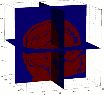 |
Reading the head binary image into matlab and plot a slice, you will find there are lots of gaps and openings in the volume. As the dimensions of these gaps are close to the sale of a few voxel, it will give iso2mesh a really bad time trying to mesh with these gaps and holes. Therefore, we first perform a binary volume repairing process: deisland3d, to fill the holes and remove the isolated regions form the image. The cleaned up version of the head image can be found at here. The brain volume is clean by itself, so, we do not need to do hole-filling and island-removing.
| The head image after hole-filling/island-removing is |  |
In this case, we will make a 2-level surface meshes: we will make 3D FEM mesh to fill both the regions between the head surface and brain surface, as well as the volume within the brain surface, and we want to make sure that the surface representation of the brain appears exactly in the resulting volumetric mesh (i.e., there is a conformal surface layer in the FEM mesh to match the brain surface). To do this, we first add the brain binary image on top of the head image, to create a two level image: voxels with value of 0 represent air, voxels of 1 represent the head region outside the brain, and voxels of value 2 represent the brain region. We pass this 3-valued array, fullimg, to vol2mesh, vol2mesh will first extract the isosurface the interface between 0 and 1, performing mesh repairing and simplification; and then the interfaces between 1 and 2. After both surfaces complete, we will produce volumetric mesh for this mesh cluster. The resulting mesh will have a exterior surface conforms to the head contour, and an internal surface to conform to the brain surface.
| The 3-level head and segmented brain image |  |
| The brain surface mesh is |  |
| The head surface mesh is | 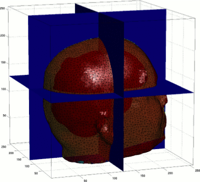 |
| The produced volumetric mesh cross-cut view 1 |  |
| The produced volumetric mesh cross-cut view 2 |  |